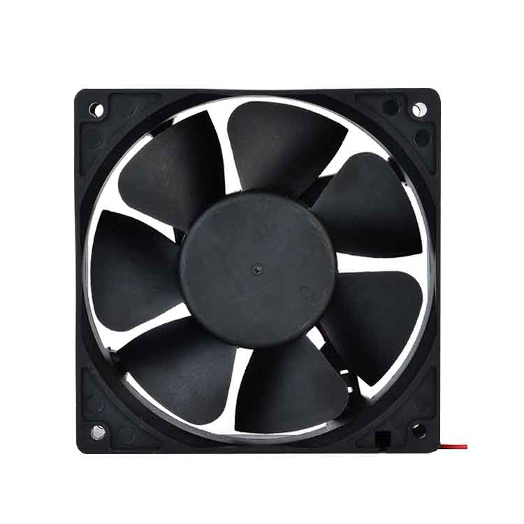
Proper thermal management is crucial for the reliability and longevity of electrical and electronic appliances. Engineers must accurately calculate the airflow requirements based on the system’s power dissipation. Insufficient cooling can result in reduced lifespan, leading to decreased customer satisfaction and potential market repercussions.
Criteria for selecting an optimal heat dissipation device are as follows:
l efficient air flow
l Minimum size and fit
l Minimum noise
l Minimum power consumption
l Reliable and long service life
l Reasonable cost
Follow these three steps to select the optimal fan or blower for your application.
Step 1. Total cooling Requirements
The first step is to recognize three key factors to obtain the total cooling requirements:
l The heat that has to be transferred: difference of temperatures (DT)
l Electrical power (W) to offset the transferred heat
l Airflow required to remove heat (CFM)
Properly assessing total cooling requirements is essential for optimal system performance. An efficient system maintains ideal operating conditions for all components, thereby maximizing their performance and extending their service life.
The following methods could be used to select fan motors:
l Determine the amount of heat generated inside the equipment
l Determine the permissible range of temperature rise inside the equipment.
l Calculate the air volume required from the equation.
l Estimate system impedance of the equipment.
l Select the fan according to the performance curve shown in the catalog or datasheet.
The required airflow volume for cooling can be determined if the internal heat dissipation and the allowable temperature rise are known.
The following is the basic heat transfer equation:
H = Cp × W × △ T
H = Amount of heat transferred
CP = specific heat of air
Δ t = temperature rise in the cabinet
W = Mass flow
We have W = CFM × D, where D = air density.
After substitution, we get
Q(CFM)=Q / ( Cp * D * Δ T )
By incorporating the conversion factors and the specific heat and density of the sea-level air, the following heat dissipation equation can be obtained: CFM = 3160 × KW / △℉
Then the following equation is obtained:
Q(CFM)=3.16 * P / Δ Tf=1.76 * P / Δ Tc
Q(M3/Min)=0.09 * P / Δ Tf=0.056 * P / Δ Tc
Q: Air flow required for cooling
P: Heat dissipation inside the cabinet (i.e., electrical power consumed by the equipment)
TF: allowable internal temperature rises in Fahrenheit
TC: allowable internal temperature rises in Centigrade
DT = temperature difference between DT1 and DT2
Example 1: The internal power consumption of the equipment is 500 watts, and the temperature difference is 20 ° F. the following are the calculation results:
Q=3.16*500W/20=79CFM or Q=0.09*500W/20=2.25M3/Min
Example 2: the internal power consumption of the equipment is 500W, and the temperature difference is 10 ℃
Q=1.76*500W/10=88CFM or Q=0.056*500W/10=2.8M3/Min
Step 2: total system impedance / system characteristic curves
Airflow within the enclosure encounters resistance from internal components, restricting its free movement. This resistance manifests as a pressure drop, measured in inches of water.
To determine the cooling capacity of each component, designers and manufacturers must consider both the fan’s performance characteristics and the system’s air resistance. Internal components obstruct airflow, creating a pressure loss that varies with the airflow rate. This pressure loss is known as system resistance.
The system characteristic curve is defined as follows:
DP= KQn
K = system characteristic coefficient
Q = air flow (cubic feet)
N = disturbing factor, 1 < n < 2
For stratospheric flow, n = 1
In turbulent flow, n = 2
Step 3: system operating point
The System Operating Point, where the system impedance curve and the fan’s characteristic curve intersect, represents the optimal operating condition for the fan in your application. At this point, the fan’s performance curve exhibits minimal change in slope, while the system’s resistance curve has the lowest change rate.
Note that the fan’s static efficiency (airflow multiplied by static pressure divided by power consumption) is also optimized at this operating point.
Design Considerations:
- Minimize airflow obstructions: Ensure the airflow path within the system is as unobstructed as possible, with clear inlet and outlet openings.
- Optimize airflow direction: Guide the airflow vertically through the system to enhance flow smoothness and improve cooling efficiency.
- Account for filter resistance: If an air filter is required, consider the additional resistance it introduces to the airflow.
Examples of Fan Selection:
Example 1.
Figure #1 is an air characteristic curve of DC cooling fan 60 × 60 × 25 mm. The fan might be applied at Point A or Point C, delivering 6 CFM or 20 CFM respectively, if the system resistance were imposed a pressure drop of 0.16(at Point A) or 0.04(at Point C) Inch-H2O on the air stream. If the system operates at point B due to improvement, the fan might be delivering 12cfm at a pressure of only 0.09 Inch- H2O.
Example 2.
As shown in Figure #2, Characteristic Curve 2 is a fan of the same size and shape, but lower speed than Characteristic Curve 1. If the system only requires 15CFM at 0.05 Inch-H2O, the intersection of static pressure and air flow curve should be through point B. Therefore, the fan provides 18CFM at zero static pressure, which is enough for cooling. Thus, the final arrangement is to choose a fan of lower speed.
Example 3.
Figure #3 shows the air performance curves of 40 × 40 × 6mm (Curve 3), 30 × 30 × 6mm (Curve 2), and 25 × 25 × 6 mm (Curve 1) medium speed DC fan.
Case 1:
If the system impedance is 0.025 Inch-H2O and 2 CFM air flow is required for cooling, 40 × 6mm DC fan is recommended( Please refer to point B)
Case 2:
If more components are added to the system and/or there is a more compact physical re-configuration, a higher system impedance will be generated. Now assume that the system impedance rises to 0.038 Inch-H2O and requires 0.85 CFM for cooling. There are two fans available for selection: 40 x 6mm and 30 x 6mm. (Refer to Operating Point A). Another option for cooling a high impedance system is a Micro DC blower.
在设计电气和电子设备时,工程师需要确定散热所需的气流量。为了防止过热,所需的气流量取决于系统中的功耗,以确保其带走足够的热量。事实表明,由于冷却系统不足,系统的使用寿命会下降,销售和价格可能会下降,因为寿命不符合用户的期望。
选择最佳散热装置的标准如下:
- 高效气流
- 最小尺寸和适应性
- 最低噪音
- 最低功耗
- 可靠性和长寿命
- 合理的成本
请按照以下三个步骤选择最适合您应用的风扇或鼓风机。
步骤1. 总冷却需求
第一步是识别三个关键因素以获得总冷却需求:
- 必须转移的热量:温差 (DT)
- 抵消转移热量的电功率 (W)
- 去除热量所需的气流量 (CFM)
正确评估总冷却需求对于最佳系统性能至关重要。高效的系统为所有组件维持理想的工作条件,从而最大限度地提高其性能并延长使用寿命。
以下方法可用于选择风扇电机:
- 确定设备内部产生的热量
- 确定设备内部允许的温升范围
- 根据方程计算所需空气量
- 估计设备的系统阻抗
- 根据目录或数据表中显示的性能曲线选择风扇
如果已知内部散热量和允许的温升,则可以确定冷却所需的气流量。
以下是基本传热方程: H = Cp × W × △ T H = 传递的热量 CP = 空气的比热 Δ t = 机柜内的温升 W = 质量流量 我们有 W = CFM × D,其中 D = 空气密度。 代入后,得到 Q(CFM)=Q / ( Cp * D * Δ T ) 通过结合转换因子以及海平面空气的比热和密度,可以得到以下散热方程: CFM = 3160 × KW / △℉ 然后得到以下方程: Q(CFM)=3.16 * P / Δ Tf=1.76 * P / Δ Tc Q(M3/Min)=0.09 * P / Δ Tf=0.056 * P / Δ Tc Q:冷却所需气流 P:机柜内的散热量(即设备消耗的电功率) TF:允许的内部温升(华氏度) TC:允许的内部温升(摄氏度) DT = DT1 和 DT2 之间的温差
示例 1: 设备的内部功耗为 500 瓦,温差为 20 °F。以下是计算结果: Q=3.16500W/20=79CFM 或 Q=0.09500W/20=2.25M3/Min 示例 2: 设备的内部功耗为 500W,温差为 10 ℃ Q=1.76500W/10=88CFM 或 Q=0.056500W/10=2.8M3/Min
步骤 2:总系统阻抗 / 系统特性曲线
当空气流动时,它将在其流动路径中遇到机柜内部零件的阻碍,并且阻抗将限制空气自由流动。压力的变化是水柱英寸的静压。
为了确认每个插槽的冷却瓦数,系统设计师或制造商不仅必须具有风扇的特性曲线以确定最大气流,而且还必须知道系统的空气阻力曲线。由于机柜内部组件的阻力,空气压力会损失。这种损失随气流而变化,称为系统阻力。
系统特性曲线定义如下: DP= KQn K = 系统特性系数 Q = 气流(立方英尺) N = 扰动因子,1 < n < 2 对于平流层流动,n = 1 对于湍流,n = 2
步骤 3:系统工作点
系统工作点是系统阻抗曲线和风扇特性曲线相交的点,代表了您的应用中风扇的最佳工作条件。在该点,风扇性能曲线的斜率变化最小,而系统阻力曲线的变化率最低。
请注意,风扇的静态效率(气流量乘以静压除以功耗)在该工作点也得到了优化。
设计注意事项:
- 最大程度地减少气流阻碍: 确保系统内的气流路径尽可能畅通无阻,并保持清晰的进气口和出气口。
- 优化气流方向: 引导气流垂直穿过系统,以增强气流顺畅度并提高冷却效率。
- 考虑过滤器阻力: 如果需要空气过滤器,请考虑其对气流造成的额外阻力。
风扇选择示例:
示例 1.
图 #1 是直流冷却风扇 60 × 60 × 25 mm 的空气特性曲线。如果系统阻力对气流施加 0.16(在 A 点)或 0.04(在 C 点)英寸-H2O 的压降,则风扇可能在 A 点或 C 点应用,分别提供 6 CFM 或 20 CFM。如果系统由于改进而在 B 点运行,则风扇可能会以仅 0.09 英寸-H2O 的压力提供 12cfm。
示例 2.
如图 #2 所示,特性曲线 2 是相同尺寸和形状但速度低于特性曲线 1 的风扇。如果系统仅需要 15CFM 在 0.05 英寸-H2O 处,则静压和气流曲线的交点应通过 B 点。因此,风扇在零静压下提供 18CFM,足以用于冷却。因此,最终安排是选择速度较低的风扇。
示例 3.
图 #3 显示了 40 × 40 × 6mm(曲线 3)、30 × 30 × 6mm(曲线 2)和 25 × 25 × 6 mm(曲线 1)中速直流风扇的空气性能曲线。
情况 1:
如果系统阻抗为 0.025 英寸-H2O 且冷却需要 2 CFM 气流,则推荐使用 40 × 6mm 直流风扇(请参考 B 点)
情况 2:
如果向系统中添加更多组件和/或进行更紧凑的物理重新配置,则会产生更高的系统阻抗。现在假设系统阻抗上升到 0.038 英寸-H2O 并且冷却需要 0.85 CFM。有两个风扇可供选择:40 x 6mm 和 30 x 6mm。(参考工作点 A)。冷却高阻抗系统的另一个选项是微型直流鼓风机。

